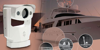
 Voyager II is a powerful, multi-sensor, mid range thermal night vision system, specifically designed for marine applications. It features two thermal imaging cameras and one daylight / low light camera. One thermal imager has a wide angle field of view and is ideal for navigation and situational awareness. The other, with the narrow field of view, allows the user to zoom in on objects that are very small or far away. The Voyager II overlays these images to provide a high resolution image without losing broad situational awareness. Voyager II is a powerful, multi-sensor, mid range thermal night vision system, specifically designed for marine applications. It features two thermal imaging cameras and one daylight / low light camera. One thermal imager has a wide angle field of view and is ideal for navigation and situational awareness. The other, with the narrow field of view, allows the user to zoom in on objects that are very small or far away. The Voyager II overlays these images to provide a high resolution image without losing broad situational awareness. |
Crisp thermal images – 320 x 240 pixels
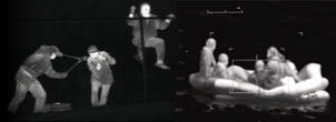
The Voyager II provides crisp, clear thermal imaging, 320 x 240 pixels, in total darkness, smoke and light fog. It allows you to see small details and detect more and smaller objects at further distance.
Advanced internal camera software
Delivers a crisp image without the need for user adjustments. The Voyager II provides high quality thermal imaging in any night or daytime environmental conditions.
Uncooled system
Both thermal cameras in the Voyager II use an uncooled microbolometer detector producing a 320 x 240 pixels high resolution image. An uncooled system means that there are no moving parts which virtually eliminates downtime and maintenance.
Two thermal imaging cameras
The Voyager II is equipped with two separate thermal imaging cameras. One has a 35 mm (20? field of view) wide angle lens, the other is equipped with a 140 mm (5? field of view) narrow field of view lens.
Continuous zoom
The Voyager II features a completely new concept in image presentation based on the foveal vision of the human eye. Foveal vision allows the operator to enjoy a wide angle view for situational awareness while maintaining a high resolution area in the center of the screen for object identification and tracking. The Voyager II accomplishes this with two independent thermal cameras and a unique patented image processing technique that provides both the foveal imaging mode as well as a continuous zoom between the wide and narrow fields of view.
Integrated long range daylight / low light camera with continuous zoom
By the touch of a button you can switch between the infrared and the daylight / low light camera. It provides you additional information and identification when conditions permit.
Designed for use in harsh maritime environments
The Voyager II is an extremely rugged system. Its vital core is well protected, IP66 rated, against humidity and water. The Voyager II can be cleaned with a hose just like any other equipment. The corrosion resistant housing protects drive motors and ensures long life. The Voyager II operates between -25°C and +55°C.
The Voyager II has a built-in heater to defrost its protective window. This ensures a clear lens and good quality infrared images displayed on your monitor even in extremely cold environments.
Advanced gyro-stabilization
The Voyager II is gyroscopically stabilized. The system compensates for practically any sea-state and allows you to see a steady image even in rougher waters.
Fast, precision Pan/Tilt system
Thanks to its precision, fast, pan and tilt system, the Voyager II allows for easy following of fast moving vessels or other objects.
Joystick control unit (JCU)
The Voyager II comes standard with a Joystick Control Unit (JCU) to operate the pan and tilt, switch between thermal / daylight image and focus / autofocus , zoom in and out.
Radar Connection – “slew-to-cue”
The Voyager II can be connected to a radar system in a so-called “slew-to-cue” configuration. The Voyager II is able to identify and track radar targets by using the National Marine Electronics Association (NMEA) 0183 protocol. The NMEA 0183 protocol allows the camera to automatically point towards vessels and other objects that show up on the radar display and to track their movement. When enabled, this means that if the radar detects an object, the Voyager II will automatically turn in the right direction and follow the object, so that you can see what the blip on you radar screen really means.
Easy-to-install
Various options exist to connect the Voyager II. It can be configured for stand alone use or optionally as part of a TCP/IP network:
- Stand alone use: Simply connect the Voyager II over the Joystick control unit. A video cable can be connected to any multi-function display that accepts composite video. - Remote control over TCP/IP The Voyager II can easily be connected to any TCP/IP network so that you can control your camera from any location in the world over the internet. It allows you to see the images produced by the Voyager II at any location on your vessel. You can check on you vessel wherever you are in the world, without being on board.
|
| IMAGING PERFORMANCE |
Detector type
Spectral range
Number of fields of view
Field of view camera 1
Field of view camera 2
Spatial resolution (IFOV)
Thermal sensitivity
Image frequency*
Focus
Electronic zoom
Visual:
Built-in digital video
Effective pixels
Standard lens performance
Optical zoom
Electronic zoom
|
Focal Plane Array (FPA), uncooled microbolometer 320 x 240 pixels
7.5 to 13µm
Two thermal imaging cameras with foveally merged video
20° (H) x 15° (V) with 35 mm lens (NTSC) - 20° (H) x 16° (V) with 35 mm lens (PAL)
5° (H) x 3.75° (V) with 140 mm lens (NTSC) - 5° (H) x 4.0° (V) with 140 mm lens (PAL)
1.1 mrad for 35 mm lens - 0.27 mrad for 140 mm lens
65mK max
7.5Hz (NTSC) or 8.3 Hz (PAL)*
Automatic or Manual
Foveal presentation: 20° to 2° FOV
Digital Detail Enhancement (DDE)
Sony FCB EX-980S High Telephoto Zoom Color Block Camera (NTSC)
Sony FCB EX-980SP High Telephoto Zoom Color Block Camera (PAL)
Approx. 680,000 pixels (NTSC) - Approx. 800,000 pixels (PAL)
26x tied to thermal zoom
up to 12x |
| PAN - TILT |
Az Range
El Range
|
Continuous 360° panning, speed tied to zoom
+/-60° |
| STABILIZATION |
| Type |
Gyroscopically stabilized |
| SYSTEM FEATURES |
Automatic Heater
Built-in Test (BIT)
Programmable Search |
Clears ice from windows
Intelligent self diagnostics tests vital functions
Programmable multiple preset scene locations with optional Software Developers Kit (SDK) |
|
| IMAGE PRESENTATION |
Video output
Connector types
|
NTSC thermal and visible - PAL thermal and visible
Corrosion resistant
BNC - BNC to RCA adapter included |
| POWER |
Requirements
Consumption |
24 V DC
<50 W nominal; 130 W peak; 270 W peak with heaters |
| ENVIRONMENTAL SPECIFICATIONS |
Operating temperature range
Storage temperature range
Automatic Window defrost
Humidity
Sand/dust
Encapsulation
Shock
Vibration |
-32°C to +55°C
-50°C to +85°C
Yes
100% relative humidity salt spray
Mil-Std-810E
IP X6
Mil-Std-810E
Mil-Std-810E |
| PHYSICAL CHARACTERISTICS |
Camera Weight
Camera Size
Shipping weight(camera + packaging)
Shipping size(camera + packaging) (L x W x H) |
20.4 kg
38.1 cm diameter x 58.4 cm height - swept volume
32 kg
85 cm x 59 cm x 41 cm |
INTERFACES |
TCP/IP
RS-422
STANDARD PACKAGE |
Camera command and control
PTZ-35x140 MS Joystick Control (PelcoD) via RS-422
Pan/Tilt head with integrated thermal imagers and DLTV camera Break-out cable with standard mating connectors, Operator manual
|
* 30 Hz NTSC or 25 Hz PAL available. Subject to approval of the US Department of Commerce for use outside the USA.
|